Calibration of Headphones
This page contains information on how to calibrate the headphones. Calibration is done to identify the output voltage of the headphone amplifier that corresponds to a certain sound pressure level (SPL) at the output of the headphones. This nominal sound pressure level is maintained as long as the output voltage of the headphone amplifier is not changed. This procedure has the advantage that the actual sound pressure level (in dB) has to be measured only once during calibration using an artificial ear and a sound level meter. After calibration, only the corresponding voltage has to be measured using a voltage meter.
Equipment
- Computer
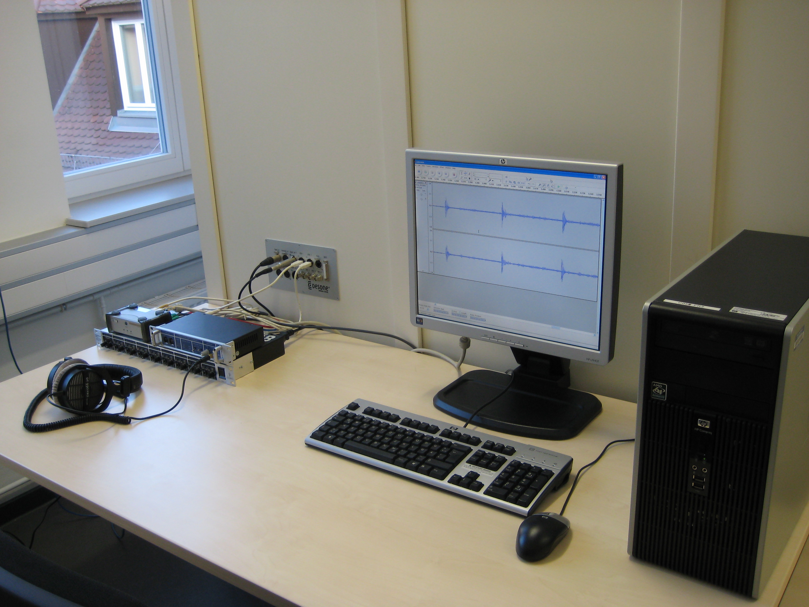
Figure 1: Controls.
- Headphone amplifier: Behringer Powerplay Pro-8 HA8000
- Sound card: RME Hammerfall DSP Multiface II
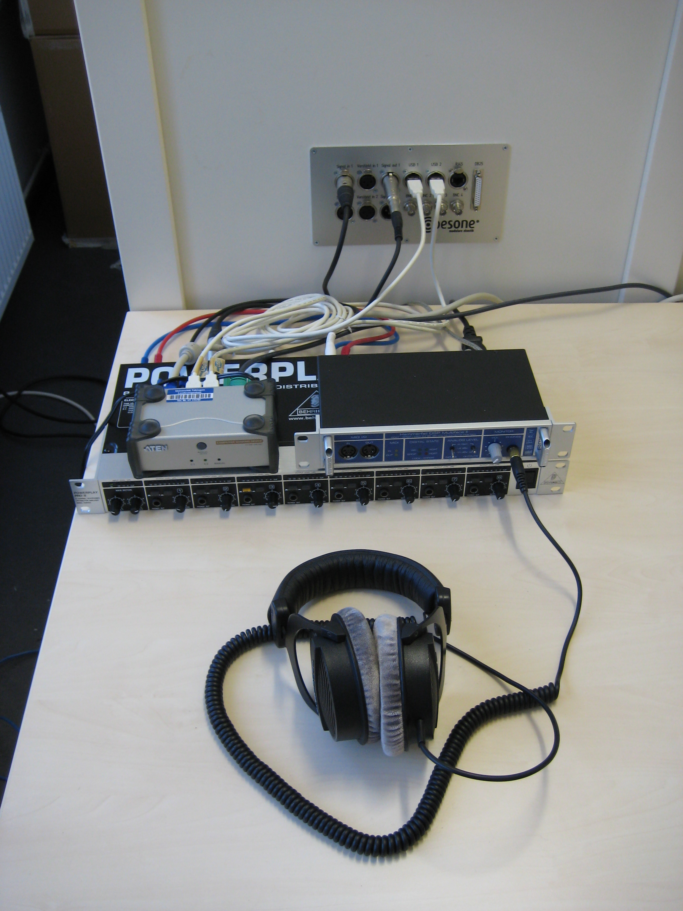
Figure 2: Hardware.
- Voltage meter: Metex M-3800
- Headphones: Beyerdynamic DT 990 Pro
- Artificial ear + metal disk with isolating ring
- Sound level meter: CEL-275
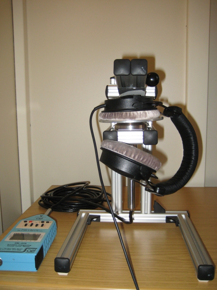
Figure 3: Artificial ear.
Preparation
Outside the Booth
Create a calibration tone with known RMS amplitude relative to full scale (dB FS). It is the goal of the procedure to determine the sound pressure level (in dB relative to \(20\,\mu\text{Pa}\)) of this tone. The SPL of any other sound can be calculated relative to the calibration tone, because the difference in dB FS equals the difference in dB SPL.
On the computer, create a folder for each experiment. Put the calibration tone into this folder. Start Audacity and play back the calibration tone in an infinite loop.
Plug the voltage meter into the amplifier as shown in the following picture.
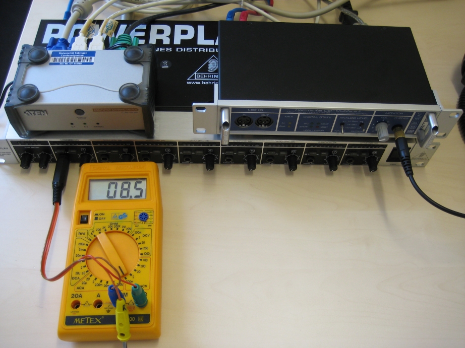
Figure 4: Voltage meter.
Connect the blue plug with the COM connector and the green (left channel) or the yellow (right channel) plug with the V/Ohm connector. Switch the voltage meter to ACV (200m).
Inside the Booth
In order to set up the artificial ear, place the microphone into the support frame.
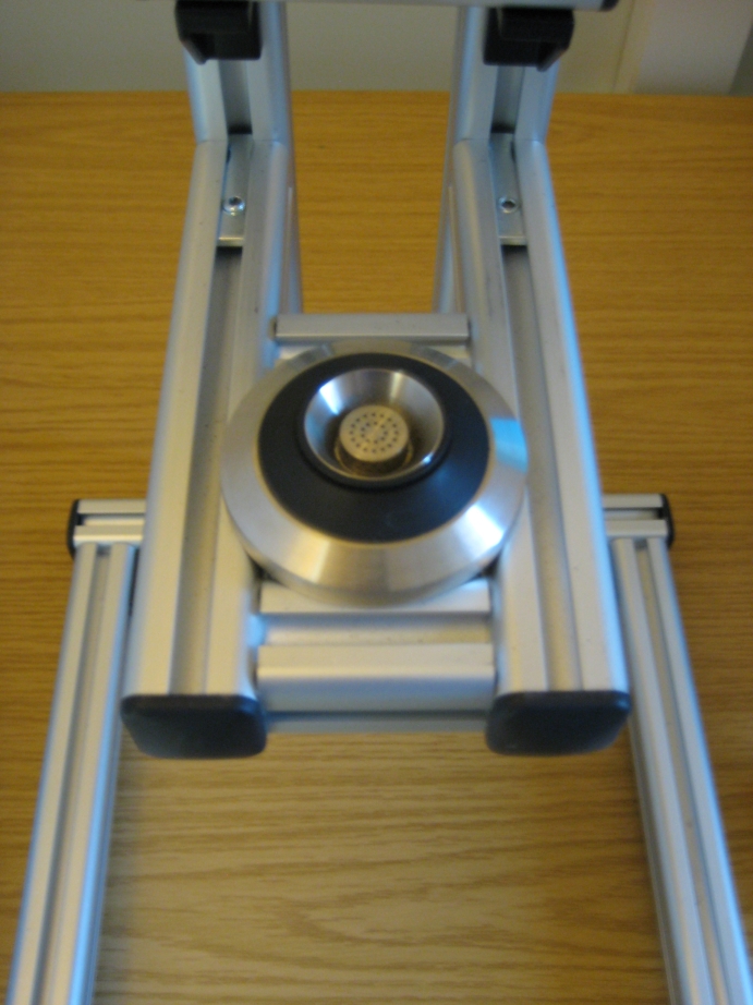
Figure 5: Coupler.
Put the metal disc on top.
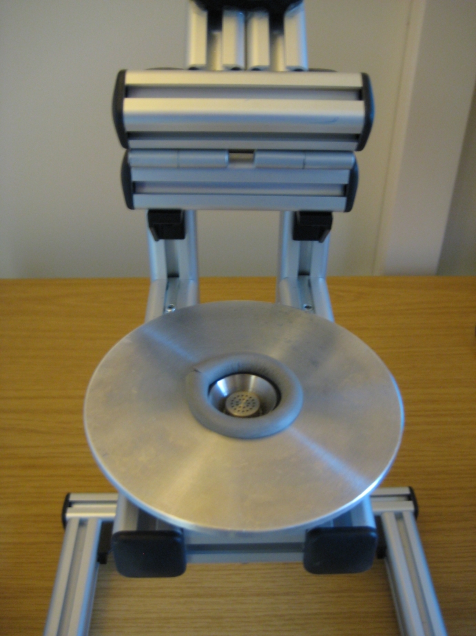
Figure 6: Coupler with metal disc.
Connect the microphone with the sound level meter (see above Figure 5: Coupler.) and plug the headphones in (on the right-hand side of the desk). Position the switches of the sound level meter as follows:
- left: 50
- middle-left: A
- middle-right: F
- right: ON
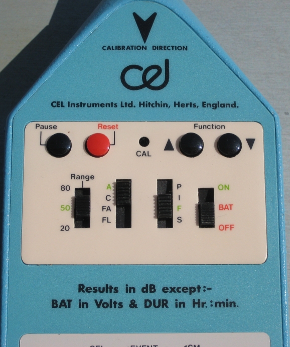
Figure 7: Sound level meter.
Procedure
- Choose the channel you want to calibrate (left or right). Plug in the respective pin (green for left, yellow for right) into the voltage meter. On the sound card interface on the computer, click M to mute the other channel (as shown in Figure 8: Sound card interface.). AN1 stands for the left, AN2 for the right channel.
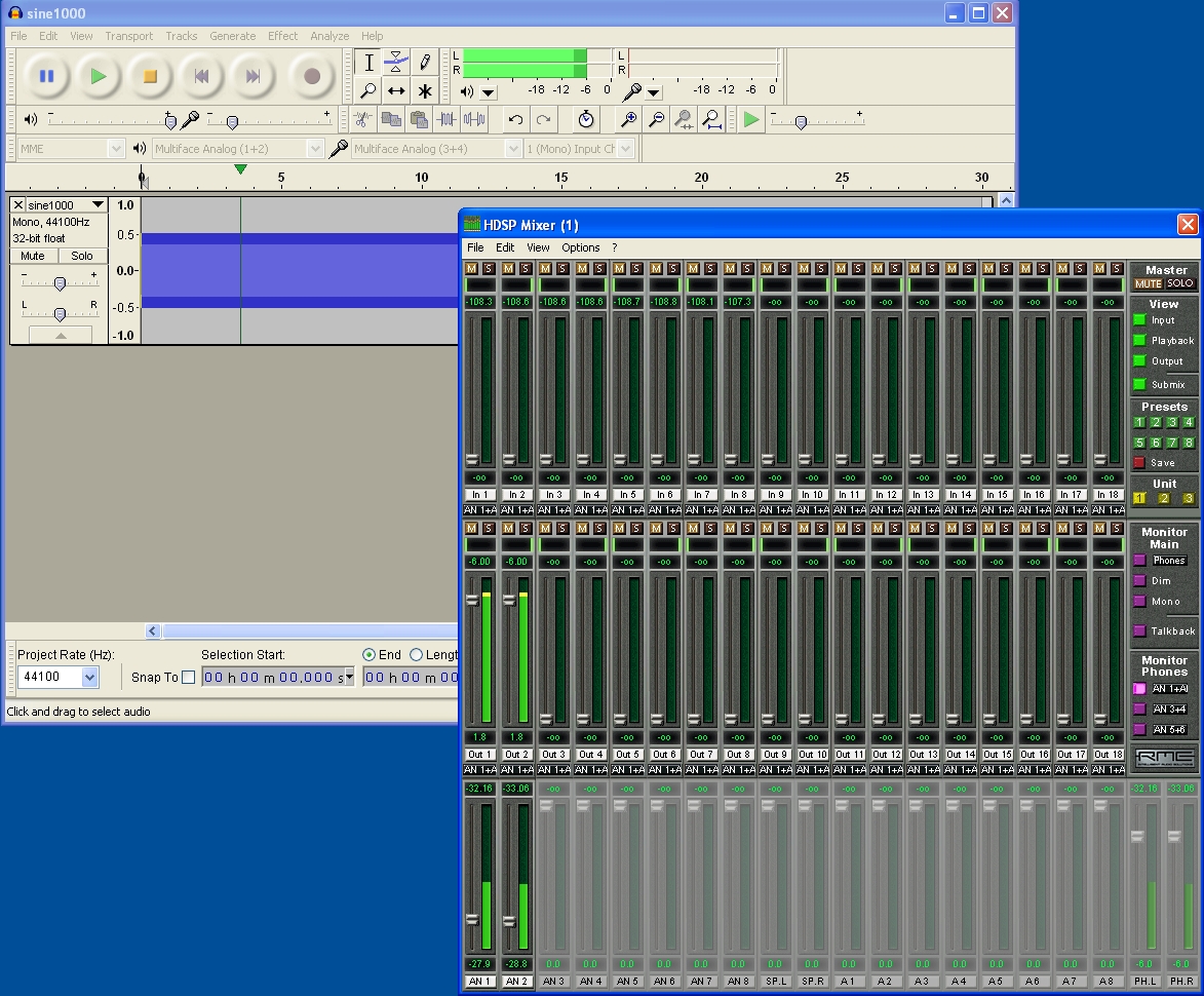
Figure 8: Sound card interface.
- Place the headphones onto the metal disc of the artificial ear and pull the arm down to fix it (see Figure 3: Artificial ear.). Close the door of the booth. Do not make any noise.
- Adjust the sound pressure level via the sound card interface on the computer until the sound level meter shows the desired SPL. Alternatively, if there is a second person present, adjust the output gain of the headphone amplifier. Both sound card and amplifier gains should be within a middle range. Once the SPL seems stable, leave the booth and note down the SPL and the voltage that is shown on the voltage meter.
- Go back to the booth, remove and replace the headphones on the artificial ear. Fix it again with the arm. Write down the SPL from the sound level meter. Repeat this at least five times.
The measured SPL values from step 4 should fluctuate minimally around the desired SPL. If the deviance is substantial, start again at step 2.
Repeat the procedure for the other channel.